Issues of Concern
Primary Ultrasound Physics Principles
The crucial physics principles needed to understand and optimize clinical ultrasound include frequency, propagation speed, pulsed ultrasound, waves’ interaction with tissue, angle of incidence, and attenuation.[3] Sound is mechanical energy that moves via alternating high and low-pressure waves through a medium. A sound source produces longitudinal wave oscillations, allowing the propagation of energy and critical waveforms for a clinical ultrasound. The high-pressure phase of a sound wave is the compression phase, whereas the low-pressure phase is rarefaction. In clinical ultrasound, the media involved are air, water, body fluid, soft tissues, blood, and bone.
Frequency refers to the number of cycles per second emitted by the probe over one second and is expressed in hertz (Hz). A period is the length of time for a complete wave cycle to occur (rarefaction and compression) and is inversely related to frequency. Similarly, the wavelength described is the distance between two adjacent wave peaks. It is important to distinguish the difference between period and wavelength; the former is a distance and the latter a length of time.[4] Ultrasound waves are conducted at a frequency greater than 20MHz, above the upper limit of human hearing. Frequency depends on the emission source and is entirely independent of the tissue that waves are interacting with.[3] Frequencies used in clinical ultrasound range from 1MHz to 20MHz, depending upon the probe used and the application desired. The frequency has a corresponding relationship with resolution and an inverse relationship with depth. The greater the frequency used, the lower the penetration, but the greater the image’s resolution.[5]
Amplitude is the height, or strength, of a wave defined by the distance between the peak and the average of the wave's highest and lowest points. Power in ultrasound refers to the square of wave amplitude, or difference between the maximum and average values, of propagated waves.[6] Both power and amplitude can be controlled by the sonographer and managed with gain adjustment. Power is measured in watts or milliwatts but can be displayed on the ultrasound machine either by decibels (dB) or the total acoustic power percentage.[4]
Intensity refers to the power delivered over a specific area, expressed in watts/cm2 or milliwatts/cm2.[4] The spatial peak is the location where intensity is at its greatest (highest power over the smallest area) and represents the focal point of ultrasound beams.
Decibels (dB) are a logarithmic expression of the ratio of two sound intensities. The dB can be determined by calculating the ratio of the sound source intensity and the least audible intensity, calculating the LOG, and multiplying it by 10. There is a simplified rule of 3dB that states with each 3dB gain. There must be an additional doubling of power delivered. Thus, a 3dB gain requires twice the power, a 6dB gain requires four times the power, and a 9dB gain requires eight times the power.
Propagation speed is the rate at which waves pass through a medium. The ultrasound waves’ speed is accepted to be 1540m/sec in soft tissue, known as acoustic impedance. Propagation speed depends on the characteristics of the medium that waves are traveling through and is independent of the frequency. As tissue density increases, the propagation speed decreases. By contrast, the stiffer the tissue, the higher the propagation speed.[4]
To achieve desired depth and resolution for clinical ultrasound, waves are emitted from the probe as pulses, typically a millisecond in duration and occurring up to several thousand times per second. This principle is referred to as pulsed ultrasound.
Ultrasound waves travel into tissue and are reflected back to the probe at a rate determined by the target tissue’s consistency. Reflections of sound that return to the probe are called echoes and are determined by two different materials' interfaces.[3] Images produced based on the echos give structures and media their varying densities on the screen, referred to as echogenicity. The more significant the difference in the density of two materials (tissue), the stronger the echo that will be produced.[3] Structures with higher density reflect more sound and are considered more echogenic (white). Thus, bone and dense foreign bodies reflect sound fully and appear bright on the screen, whereas fluids such as water or urine reflect no sound to the probe and appear anechoic (black).[6] Weak echos appear gray. When waves echo back to the probe from material such as bone and air, which cannot propagate sound, sound waves cannot pass to deeper tissue and a shadow behind the interface results.
The angle at which ultrasound waves engage with any structure is referred to as the angle of incidence. Structures are ideally imaged with the angle of incidence perpendicular to emitted waves because echoed waves return to the probe in the greatest concentration.[3] When waves interact with a structure obliquely, fewer waves echo back to the probe, decreasing both the structure brightness and resolution. Waves hitting a structure obliquely return to the probe at an angle equal to the angle initially striking the structure’s boundary.[3] If the angle is not directly perpendicular to the incidence angle, the wave will reflect away from the source.[4]
Similarly, waves are deflected from a straight line when waves’ velocity differs between two structures and results in refraction.[3] The original angle of incidence and the difference in the two media’s propagation speed determine the refraction's ultimate angle. Refraction is a source of artifacts in ultrasound, considering that all ultrasound machines operate under the assumption that waves will always travel and return in a straight line.[3]
Different tissue interfaces reflect differently and contribute to image quality. Smooth interfaces are considered specular reflectors and return a high proportion of waves to the transducer. Specular reflectors are contrasted against irregular interfaces called diffuse reflectors, which cause sound waves to reflect away from the transducer and reduce the image’s quality. An important type of scattering, called Rayleigh scattering, occurs when an object is smaller than the ultrasound beam’s wavelength. Red blood cells display this scattering type, resulting in waves scattering in all directions.[4]
Considering that ultrasound waves cannot travel through the air, probes must contact patients’ skin through a coupling medium to engage with tissues. Coupling occurs through the use of ultrasound gel or water baths. As ultrasound waves interact with tissue and reflect the probe, the energy associated with any remaining beams decreases with increasing depth. The strength of penetrating waves is reduced by refraction, scattering, and absorption.[5] When waves are scattered and energy absorbed, it results in vibration energy and heat. All of the processes that contribute to energy reduction are collectively referred to as attenuation.
Wave attenuation, or the decrease in intensity over a given distance, is also measured in decibels (dB) and occurs at a rate per centimeter roughly equal to the frequency emitted initially. Thus, a 5MHz wave will attenuate at approximately 5dB in the first centimeter and another 5bB in the next centimeter. Ultimate wave penetration is determined by the depth at which the intensity of the waves is reduced by 50%, in a reverse fashion used to determine the dB gain described above. Thus, the depth at which 50% of the intensity is attenuated is equivalent to a loss of 3dB. Higher frequency waves and waves for deep imaging are attenuated more quickly than low-frequency waves or waves used for shallow imaging.[4]
Gain (power) can be adjusted over the entire image or, depending on the machine being used, at different depths to visualize structures at those depths best. Additionally, deeper structures must use lower frequencies to become visible. Such visibility comes at the expense of resolution, which is improved with higher frequencies. Sonographers must manage the frequency being used to balance the need for both depth and resolution depending on the ultrasound application for any specific target structure.
Transducers
Transducers are the instruments that emit and receive ultrasound waves by way of electrical signal conversion to sound waves. Ultrasound transducers contain piezoelectric crystals that, when electrical impulses are applied, produce waves at frequencies determined by the crystal’s propagation speed, divided by two times the thickness of the crystal layer. The typical thickness of crystal layers is between 0.2mm and 2mm. The bandwidth of a particular probe is the range of frequencies at which the probe will operate.
Transducers can both send and receive ultrasound waves by applying energy and, ultimately sound waves, in pulses. The pulsatile nature of ultrasound waves produced facilitates the emission and reception of sound waves. When incident pulses reflect off tissues, producing echoes, the device can detect the strength, direction, and timing of arriving echoes.[3] The number of pulses produced in a single second is the pulsed repetition frequency (PRF), and the pulsed repetition period (PRP) is the time between the start of two pulses. The PRF and PRP, like with period and frequency described above, are inversely related to one another. Higher PRF will equal greater image resolution but shallower depths, whereas higher PRP and increased “listening” time from the transducer will allow greater depth.[4]
Typical transducers used in clinical ultrasound include linear array, phased array, and curvilinear array, which has multiple configurations and frequencies depending on the application needed. The transducer face’s crystals and structure's arrangement determine the area and shape of the image produced. Linear arrays have flat faces that produce a rectangular image. Phased arrays have crystal configurations and power sequences that steer beams from a single point to create a sector image ideal for scanning between ribs.[7] Curvilinear arrays have curved surfaces of various radii that also can be used across multiple bandwidths depending on the application desired. For example, low-frequency curvilinear transducers are often used for abdominal exams because of the deep penetration and wide field of view. In contrast, high-frequency endocavitary curvilinear transducers are used for female pelvic exams due to their high resolution and small footprints.
Managing Images
Frequency
Selecting a probe with the appropriate bandwidth is an essential consideration to ideal image acquisition. For general scanning presets, machines are often set to “GEN,” or general, typically the middle range for the probe bandwidth. If higher resolution is required to evaluate a structure, the frequency can be increased on the machine directly or using available “RES” for resolution. The increased frequency will sacrifice penetration depth. The reverse is true if greater penetration is needed. Frequency is decreased directly or by using the “PEN” or penetration setting.
Gain
When attenuation must be managed, either because a target is too bright or too dark, power can be increased or decreased either throughout the entirety of the image or at specified depths. Gain increases will add power to combat attenuation by increasing the brightness.[5] Gain decreases lower the power and the overall brightness. When images are over-gained or under-gained, the resolution worsens.
Time Gain Compensation
Time gain compensation refers to power controls at specific image depths to combat the attenuation with depth. This helps improve deep structure imaging, mainly if deep tissue is subject to posterior acoustic enhancement. This feature is often seen with “slider bars” seen on the ultrasound console.
Depth of Field
The depth of field is the depth to which sound beams are transmitted and received. Depth is altered on display to optimize the power and temporal resolution of the machine to view target structures.[4] The depth must be significant enough to see deep structures when needed and shallow enough to see shallow structures with adequate resolution. When depth is set too deep for superficial examinations, the target structure image’s quality is degraded.
Focal Point and Resolution
Ultrasound beams leave the transducer at the same width as the face. They travel through the near zone before narrowing at a focal zone and widening in the far zone. The resolution, or the ability to discern two closely situated objects, and lateral resolution is best in the focal zone. Spatial resolution can also be improved with higher frequencies, smaller pulse repetition frequencies, and short pulse duration. The axial resolution, or the ability to discern two structures in the path of the beam, is generally better than lateral resolution, or the ability to distinguish two side-by-side structures due to ultrasound beams being shorter than they are wide. Lateral resolution is greatest at the focal point where the beam width is most narrow. Temporal resolution, or the time the machine takes to create an image, is inversely related to the frame rate. Higher frame rates produce lower resolution images, and lower frame rates have higher resolution images. Frame rates of at least 15 frames per second produce real-time images.[6] Temporal resolution is most important with moving objects, and if the frame rate is too low, supporting a high temporal resolution, the ability to detect motion diminishes. Additional augmentation tools, such as microbubbles, add resolution capability by strongly reflecting ultrasound beams, particularly in vasculature.[8]
Multibeam
Modern ultrasound transducers are created to send ultrasound signals out at multiple angles across the probe’s face. They produce multiple angles of incidence that have multiple angles of reflection back to the probe receiver. This helps to improve image quality, especially around structures that would otherwise be prone to refraction artifacts.
Tissue Harmonics
Tissue harmonics refers to tissue’s tendency to resonate at multiples of the incident frequency transmitted by the probe. For example, when 3MHz waves are transmitted to tissue, the tissue will resonate at 3MHz, 6MHz, and 9MHz. Transducers can be set to receive the incident frequency and the harmonic frequencies, combining them to create a higher resolution image. Using tissue harmonics settings also assists in reducing artifacts.
M-Mode
M-Mode, or time-motion display, allows a single beam to emit from the transducer along a defined track in conjunction with a recorder that captures all motion that occurs along the path. This mode allows high temporal resolution, thus affording the examiner an excellent view of subtle motions.[5] Clinically, this mode is ideal for capturing vessel diameter changes, movement of cardiac valves, and detecting fetal heartbeats.
Artifacts
Artifacts are image errors that are interpreted by the ultrasound machine related to the physics principles discussed previously. They are often the result of assumptions that ultrasound waves always travel in straight lines, that all tissue transmits sound at 1540 m/sec, and that waves are always reflected in the transducer directly.[9] Understanding artifacts' nature is vital to sonographers and those interpreting images because artifacts are often used as clues to detect specific pathologic findings.
Reverberations
Reverberation artifacts result from sound waves bouncing between a smooth reflector and the transducer face.[10] These appear as regularly spaced lines at intervals equal to the distance between the transducer and the structure. Common, normal findings resulting from reverberation artifact are “A lines” in lung fields.
Posterior Acoustic Enhancement
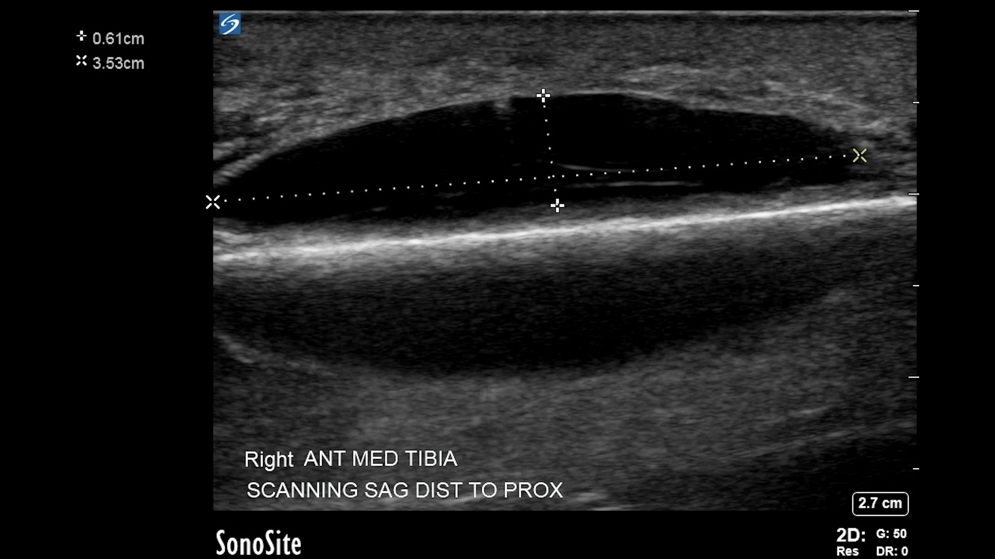
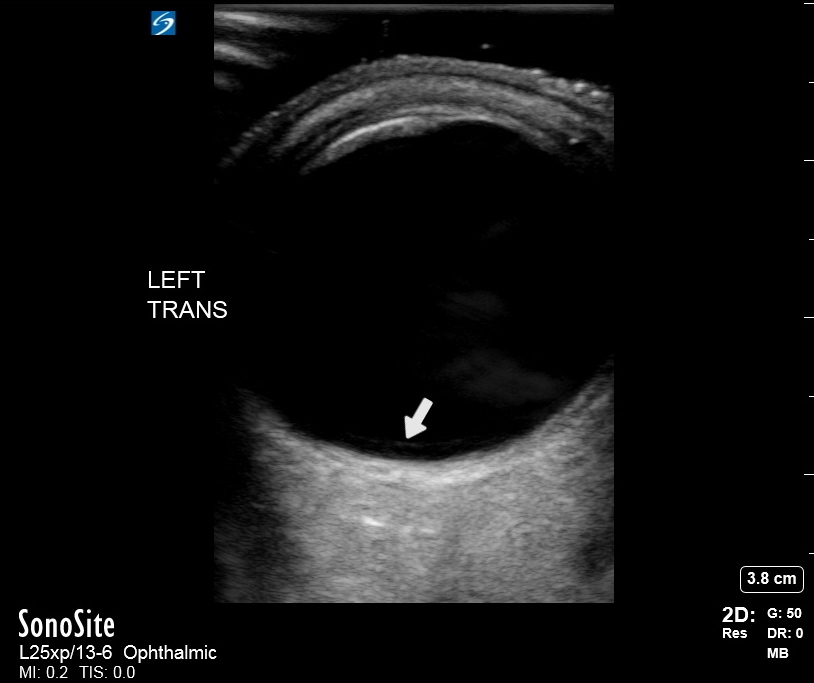
Fluid has a higher propagation rate and less attenuation than soft tissue. As a result, sound waves travel to and return from tissue deep to fluid-filled structures faster than sound waves in adjacent, non-fluid-filled structures.[10] When transducers receive sound more quickly and with higher intensity, the image produced behind the fluid-filled structure will appear bright compared to surrounding tissue. The hyperechoic signal may obscure detail in the tissue. A common application to illustrate posterior acoustic enhancement is bladder ultrasound, where time gain compensation must often be decreased to best evaluate tissues deep into the bladder. Unexpected posterior acoustic enhancement can also be a diagnostic clue that fluid is present in locations representing pathologic processes, such as in the abdomen or pleural space.
Shadows
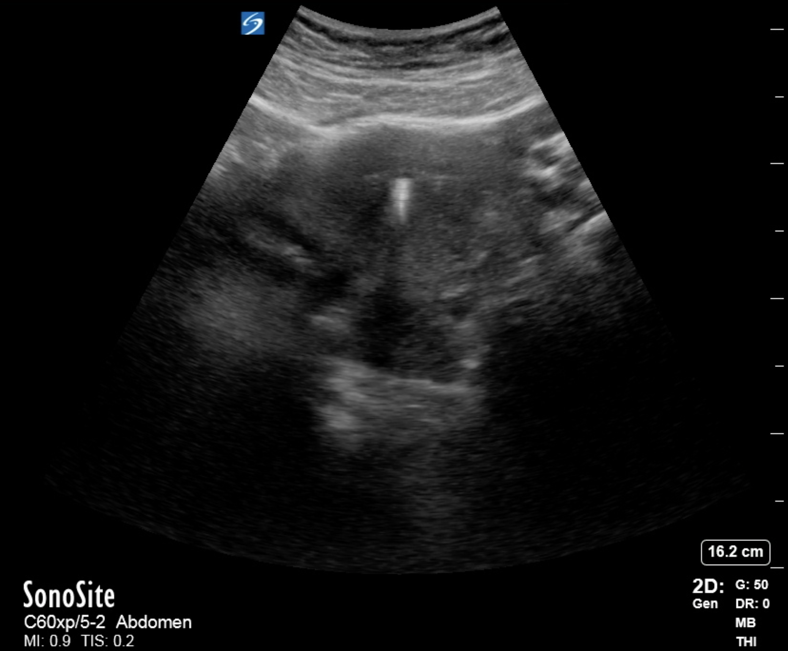
Structures of high density are highly reflective, returning the majority of sound waves to the transducer and allowing almost no waves to penetrate deep tissues.[3] The resulting structure image shows a bright, hyperechoic line or density with a dark, hypoechoic shadow behind it. Bone, metal, plastic, wood, glass, and calcium stones are of sufficient density to be so reflective and create “clean” shadows deep. On the other hand, while not dense, air also does not transmit ultrasound waves to deep structures. Air interfaces are also highly reflective but typically create less discernible shadows. Air interfaces with shadowing are typically noted in the lungs and within the bowels and may be referred to as "dirty" shadows.
Mirror
When sound bounces off a strong, smooth reflector, the transducer may reflect the pulsed wave that causes the machine to believe that the tissue interface is deep and is the same as the tissue interface to the superficial structure.[3][10] This is commonly seen with viewing the diaphragm through the liver, where machines will display the liver below and above the diaphragm.
Ring Down
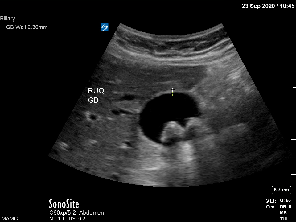
Ring down artifacts occurs when tiny bubbles or crystals resonate at the same frequency as the emitted ultrasound frequency, which emits waves of their own. Sound received from these arrives after the original echoes and is interpreted by the machine as deep structures.[3] The resulting artifact appears as a hyperechoic line deep to the offending structure, often referred to as comet tails. Ring down artifacts is of diagnostic utility for cases of adenomyomatosis of the gallbladder when the gallbladder walls are infiltrated with cholesterol crystals.[10]
Refraction
Refraction artifacts, often referred to as edge artifacts, occur when incident ultrasound waves interact with structure interfaces at angles other than 90 degrees. The difference in structure density promotes the refraction or bending of sound waves off the surface. The result is that echoes do not return to the transducer from an area expected to reflect echoes, and thus a shadow is produced.[9] This artifact is commonly seen when viewing round structures, such as the gallbladder, where shadows will follow the edges, corresponding to the walls as fanning occurs through it.