Issues of Concern
X-Ray Production
X-rays are a form of electromagnetic radiation (also called radiant energy), a type of ionizing radiation (meaning radiation with enough energy to detach electrons from atoms or other molecules) that transports energy utilizing waves and photons. A photon's energy can be described by characteristics such as frequency, wavelength, and constant speed (the speed of light; 299,792,498 m/s). Generally speaking, the photon's energy is inversely proportional to its wavelength. It is directly proportional to its frequency, meaning there are higher energy photons with a shorter wavelength and higher frequency. Energy transmitted as electromagnetic radiation is used to characterize radiation into different groups, such as radio-waves, microwaves, ultraviolet light, and X-rays. The wavelength of X-rays is typically in the range of 0.01nm to 10nm, and the associated frequency of X-rays ranges from 3x10^19Hz to 3x10^16Hz. These concepts become important in discussing the controlling factors of X-ray production later in this article.[1][2][3][4]
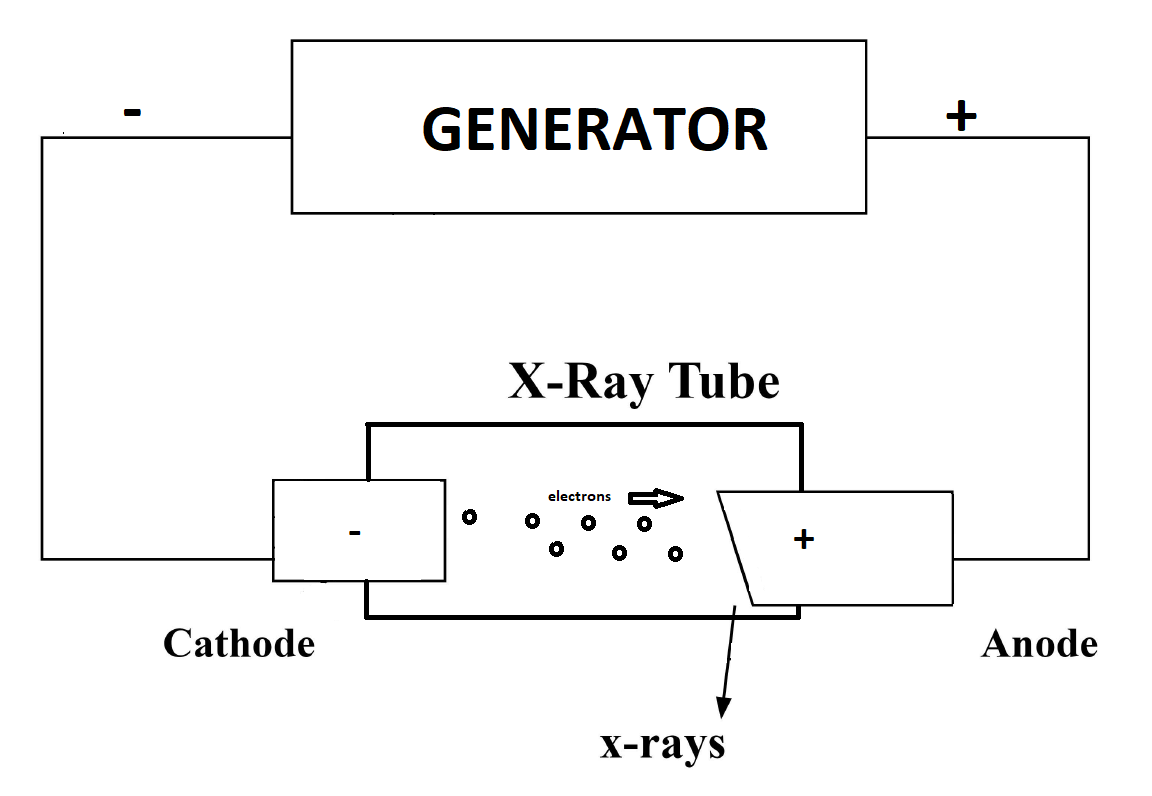
X-ray tubes are vacuum tubes that are used to convert input electrical power to X-rays. Essential components of the x-ray tube and housing include a negatively-charged cathode filament, a positively-charged anode target, a glass envelope, and lead tube housing. Producing X-rays in a tube generally requires three essential steps: the proper assembly of a tube with a source of electrons, a means to accelerate the electrons, and then decelerate the electrons.
The cathode filament serves as an electron source that, when heated by electrical current (measured in milliamperes, mA; produced by a high-voltage generator) flowing through it, produces an electron cloud called a "space charge." The process by which heating a cathode results in electrons' emission has been named "thermionic emission." There is a limit to the total amount of electrons produced from an anode in this process and can occupy the space charge at one time. This is known as a phenomenon named the "space charge effect," which happens when the current being sent through the cathode is around 1000mA. Beyond this, too much heat is produced, and it can cause the cathode to break.
The accumulation of electrons at the cathode results in a large negative charge that results in the acceleration of electrons towards the anode target. The cathode of an X-ray tube is made of a tungsten filament. X-ray tubes tend to have two pieces of tungsten per anode (dual-focus tubes), one measuring 1 centimeter in length and the second measuring 2 centimeters in length. The smaller the filament, the smaller the current the filament can handle, and the fewer electrons the filament can produce. The smaller filament is used to take radiographs of smaller body parts. The larger filament is used for larger body part imaging. Because of the increased amount of electrons in the beam, there is increased repulsion amongst the beam's electrons, creating scattering of the beam and decreased spatial resolution of radiographs. This is corrected for by having a negatively charged focusing cap at the end of the cathode, which repels the electrons away from the peripheral areas and creates a very narrow, focused electron beam, increasing spatial resolution. Now that the electrons have been excited and emitted from the tungsten filaments, they are accelerated towards the positively-charged anode.
The anode is where electrons are decelerated; the energy from deceleration is then released in the form of heat and X-rays (photons). Approximately 99% of the energy is emitted in the form of heat and 1% in the form of X-rays. There are two types of anodes: stationary anodes and rotating anodes. Stationary anodes cannot absorb as much heat (low heat capacitance) and, because of this, are not commonly used in medical imaging. Rotating anodes are made from an anode disc which rotates with the help of an induction motor. The induction motor is made from stators (electromagnets) surrounding the rotor, activated in series to induce rotation of the rotor, which rotates the anode disc. This significantly increases the heat capacity of the anode and allows it to produce more X-rays. Once X-rays are produced through this process, they must be directed properly out of the X-ray tube housing.
X-ray tube housing is composed of an inner envelope made from Pyrex glass, which keeps the X-ray tube protected and creates a vacuum around the tube to prevent corrosion and oxidation. This glass envelope has a target window for the X-rays to travel through, thinning the glass envelope. Surrounding the glass envelope is the outer portion of the tube housing, made from lead, which prevents X-rays from escaping the tube housing. Once the X-ray is produced and makes it out of the tube housing, it then travels through a lead filter. The lead filter prevents low-energy X-rays that have been emitted from the X-ray tube from reaching the patient, as these X-rays will not have enough energy to pass through the patient and contribute to the radiograph. The X-rays then pass through a collimator.
Collimation is the process of "focusing" an X-ray beam on a specific target using lead plates. The X-rays shot from the beam move through the collimator, and said plates absorb any X-rays that are not parallel with the lead plates. This produces X-rays that increase the spatial resolution of the resultant radiograph. Proper collimation is important, as X-ray beams that are over-collimated may hide diagnostically useful details, and under-collimation can expose extra radiation to patients and result in increased scatter radiation. The collimated X-rays then travel through the patient, through the lead grid behind the patient (which only allows parallel X-rays to pass through), and onto the imaging cassette.
In summary, an X-ray beam is produced by an X-ray tube, travels through a lead filter, is collimated, passes through the patient, passes through a lead grid, and then hits the imaging cassette to produce a radiograph.[2][5]
Controlling Factors of X-Ray Production (mAs and kVp)
Controlling factors of X-ray production that are manipulated by X-ray technicians to produce technically adequate images include the number of photons being produced by an X-ray beam, measured in milliamperes per second (mAs), and the energy of the photons that are being produced, measured in peak kilovoltage (kVp). The mAs reflect the image quantity/intensity, and the kVp reflects the image quality. The specific combinations used may vary depending on the patient's clinical scenario being imaged and the radiographer's experience taking the image.
Increasing the mAs of an X-ray comes from increasing the current being sent through the X-ray tube's cathode, which results in increased photons in the X-ray beam being shot towards the patient. Having too low a mAs may result in "quantum mottle," which is essentially X-ray noise. In this scenario, there are not enough photons reaching the X-ray cassette, and important details from images may be missing or unable to be seen well. On the other hand, when mAs is too high, more photons are being shot from the X-ray tube, and the patient gets overexposure to radiation. An additional factor to consider when manipulating mAs is that it is a time-dependent variable. If the electrical current is held constant, the amount of photons a patient is exposed to is entirely dependent on the amount of time they are in front of an X-ray beam. Ideally, a patient is imaged in as little time as possible with a higher electrical current so that there is a reduction of motion artifact during an X-ray.
As for kVp, when this value is increased, the photons of the X-ray beam are of higher energy and can penetrate through tissues more easily. This is due to an increase in the potential difference between the cathode and the anode, resulting in electrons being excited to higher energy levels when accelerated towards the anode. The resulting X-rays produced at higher kVps are at higher frequencies, allowing them to pass through more tissues, meaning more photons hitting the imaging cassette, creating darker radiographs. Depending on where in the body a radiographer is imaging, the kVp is manipulated as such so that there are enough photons, both penetrating tissue and attenuating tissue, to produce clinically useful contrast on radiographs. If the kVp is too high, more photons will hit the cassette, and the radiograph will appear too dark. If the kVp is too low, more photons will attenuate in the body's tissues and appear too bright.
The above concepts of mAs and kVp are important for radiographers to produce technically adequate radiographs.[6]
X-Ray Interactions
Tissue-specific absorption and attenuation of X-ray photons with resultant variable loss of photon energy and subsequent detection by the image receptor produces the variable densities seen on a radiograph. X-ray energy traveling through the body typically will result in one of three outcomes: absorption, transmission, and scatter. In general, more dense materials (e.g., bone) absorb more energy (X-ray photons) than that of less dense material (e.g., fat.) The patient's tissues will absorb approximately two-thirds of X-ray photon energy produced by X-ray tubes. About one-third results in scatter radiation, and less than 1% is transmitted to the image cassette/receptor to create a radiologic image.
Scatter X-rays are X-rays that do not hit the digital detector and are also not absorbed into the tissue. These X-rays “scatter” throughout the room and can be absorbed by personnel who do not practice proper radiation safety. A few important scatter concepts to know about include the Photoelectric effect, Compton scatter, and coherent scatter.
The photoelectric effect happens when a photon from an X-ray beam interacts with an inner electron shell and results in an ionized, low-energy electron (photoelectron) that is ejected from its' orbit (secondary radiation). During this process, the X-ray photon is completely absorbed, and there is a subsequent filling of this inner electron shell by outer-shell electrons. The photoelectric effect results in no transmitted photon through the patient to the imaging cassette. This type of interaction predominates in X-ray beams with 30 kVp and below and happens more frequently in denser substances with higher atomic numbers (e.g., bone.)[7]
Compton scatter is when an X-ray photon hits an electron in an outer shell of an atom and results in the production of both a lower-energy scattered X-ray photon and an ionized electron, which is immediately knocked out of orbit. This scatter occurs at all energy levels but begins to predominate at higher kVps. Compton scattering is undesirable in medical imaging. It "fogs" the image because of photon scattering, causes biological damage to tissue, and is the reason for radiographer exposure to X-ray radiation. It also increases the patient's dose of radiation. Patients with larger body habitus are at increased risk for Compton scatter, as there is more soft tissue density for X-ray photons to travel through. Compton scattering is one reason it is so important for radiographers to understand and apply the concepts of mAs and kVp, as proper manipulation of these two values can significantly reduce the amount of Compton scatter in a radiograph. [8]
Coherent scattering is when a photon interacts with an entire atom; the photon is temporarily absorbed. The photon is released as a lower-energy scatter photon with no ionization event, no free electron, and no biological harm. Coherent scattering is less important to medical imaging, as these effects have minimal impact on image contrast.
The collimator mentioned previously is supposed to help reduce the amount of scatter radiation in each performed radiograph, but there is always some degree of scatter radiation. Additional methods to help reduce scatter include the grid placed behind the patient and in front of the image cassette/receptor. Different scatter grids will have different grid ratios, which is the height of the lead strips (H) divided by the space between the strips (D). The standard grid ratio is approximately 10 with 45 lines per centimeter of the scatter grid.[9]
The absorption of X-rays means the energy hits the X-ray photon's target organ, and the energy is dispersed throughout the tissue through the photoelectric effect discussed above. Tissues where more energy is absorbed (e.g., bone) are said to be higher “attenuated” than those that absorb less energy (e.g., fat). From a safety standpoint, absorbed radiation per unit of mass, the "absorbed dose," is measured in grays (Gy). However, because not all types of radiation produce the same biological effects, the dose equivalent or "effective dose," measured in sieverts (Sv), is used instead, which implements a tissue-weighting factor based on the type of radiation to take into account potential biological effects of a given radiation dose.
Transmission of X-rays means the X-rays photons have passed through the patient and hit the photosensitive detector (historically called a “cassette”) on the patient's other side. This digital detector detects the X-ray photons that have hit it and converts it into an electrical signal used to represent different pixels, which are then put together to produce the conventional radiograph (colloquially called an “X-ray”). This is done by scintillators (phosphors) that emit light in the digital detector when exposed to radiation. The scintillator's emitted light is then detected by a light detector, which converted the information into a pixellated digital image. Digital detectors exposed to a small amount of radiation by manipulating the mAs and kVp may result in "noisy" images that degrade image quality. On the other end of the spectrum, digital detectors exposed to a large amount of radiation may not necessarily affect image quality but do expose the patient to unnecessary radiation. In comparison, analog radiographs (less commonly used) use film to capture, display, and store radiographic images. An analog radiograph film is made from a thin emulsion with support from Mylar (thick polyester). The emulsion contains silver halide grains, which, when exposed to radiation, become sensitized. Once the film is passed through a developer and fixer solution, the film may be hung on a lightbox for viewing.[10][11]
Radiation Safety and Exposure
Radiation damages tissues through two mechanisms: direct injury and indirectly through free radical creation, which alters cellular function. Effects of radiation exposure can be further classified as "deterministic" and "stochastic." Deterministic effects of radiation exposure are predictable effects in severity that have a certain likelihood of occurring at given radiation exposure (e.g., skin erythema generally occurs in a 2 Gy radiation exposure). Deterministic effects of radiation exposure are considered to be "nonrandom" effects of radiation exposure. Stochastic effects from radiation exposure are those effects that can occur at any level of radiation exposure and are considered "random" effects from radiation exposure. The severity of stochastic effects at a given radiation exposure is random, but their likelihood does increase with a larger radiation dose.[12] For X-ray beams used to produce radiographs, 1 Gy is equal to 1 Sv.[13] The radiation doses in medical imaging are typically expressed in millisievert (mSv). For reference, the average yearly background radiation dose from radon gas in the home is approximately 3 mSv.[14] In contrast, the standard radiograph used in medicine has an average radiation dose of about 0.1mSv. It is known that over 100mSv doses have deleterious effects on humans, such as the development of cancer, but the effects of lower doses are less clear. [13] Because accumulated radiation dose over a persons’ lifespan can cause such effects, radiology as a whole follows the ALARA principle, which says patients should always receive radiation doses that as “As Low As Reasonably Achievable.”[15] However, standard medical radiographs are generally considered very safe with minimal risk.
Technical Evaluation
Depending on how a radiograph is taken, different tissues and anatomical structures may appear to have different attenuation and may even alter the size and location of organs. Because of this, it is important to thoroughly evaluate whether or not a radiograph taken is technically adequate so that accurate clinical decisions can be made.
Technical evaluation of radiographs is necessary so they can be interpreted with confidence and precision. Interpretation of radiographs without first confirming that the image is technically adequate can lead to incorrect imaging assessment that can ultimately lead to improper patient management and negatively impact clinical outcomes. Images should be looked over by both the performing technologist, the interpreting radiologist, and even clinical staff outside of this directly involved patient care to minimize mistakes. There are several things to look for when assessing the technical adequacy of a radiograph, such as the following:
Labeling
Initial assessment of the technical aspect of a radiograph should involve confirming that the study is of the correct patient, has been performed on the correct date, and is labeled correctly (e.g., left and right.) [16] Obvious problems may arise if one scans a patient and saves the image under the incorrect patient name in the Picture Archive Communication System (PACS). It would be troublesome to input the study's incorrect date in a similar light, comparing images to previous similar images to evaluate medical imaging.
Artifact
An artifact on an image is a feature that does not correlate with the physical properties of the subject being imaged and may confound or obscure the interpretation of that image. Because the mechanism for image creation is different between flat-panel detectors and computed radiography, the causes and appearances of some artifacts can be unique to these different modalities. Artifacts can occur for several reasons; examples include damage to X-ray detectors, liquid contamination of X-ray detectors, backscatter radiation detection, and image saturation. The typical appearances of the aforementioned artifacts on chest radiography are listed below.[17]
- Damage to X-ray detectors: white banding that can progressively grow over time
- Liquid contamination: repeated vertical banding
- Backscatter radiation: shadow image of superimposed digital detector electronics
- Image saturation: clipping of anatomy
Five Anatomic Technical Assessments of Chest Radiographs
Some of the more common criteria to assess radiographs, specifically chest radiographs, are penetration, inspiration, rotation, magnification, and angulation. “PIRMA” is a helpful mnemonic that can help one remember these five criteria.
1. Penetration
One of the most useful properties of X-ray beams has been their ability to penetrate through otherwise opaque objects.[18] The amount of penetration an X-ray beam has depends on the thickness, density, and type of material in the X-ray beam's path. In medical physics, the most common way to quantify an X-ray beam's penetration is with the half-value layer (HVL), which is the thickness of a material that reduces the intensity to fifty percent of its initial value. In medical imaging, it means being able to see the thoracic vertebrae through the superimposed heart. In an under-penetrated chest X-ray, you will not be able to see the thoracic spine through the superimposed heart. In an over-penetrated chest radiograph, lung markings become difficult to see.
2. Inspiration
Adequate inspiration on a chest radiograph is generally defined as being able to visualize eight to ten posterior ribs at the midclavicular line.
3. Rotation
Rotation is assessed by measuring the distance from the medial end of the clavicles on both sides to the thoracic vertebrae's spinous process, which should be at the midline. In an adequate study, this distance should be nearly the same, meaning the patient is not rotated. If a patient is rotated to the left, the distance from the left clavicle's medial end to the spinous process will be larger than that of the distance from the right clavicle's medial end to the same spinous process. [16]
4. Magnification
Magnification refers to how large the heart appears on a chest radiograph. One can quickly and conveniently determine whether the heart is the proper size by assessing the cardiothoracic ratio (CTR). The cardiothoracic ratio is determined by measuring the heart's widest diameter on a chest radiograph, then measuring the thoracic cage's widest internal diameter, usually directly above the diaphragm. The heart's measured diameter is then divided by the thoracic cage's measured diameter to yield the CTR.[19] Generally speaking, a CTR of less than 0.5 is considered normal, although some research has questioned this convention, suggesting that normal CTR should be lower.[20] Other research has suggested using measurements in centimeters (cm) to assess normal heart size, stating that a heart with a transverse diameter of 15cm or an increase in the transverse diameter of 1 to 2 cm over a year can be called cardiomegaly. It is also important to point out that just because the heart does not appear enlarged on a chest radiograph does not mean there may not be an underlying cardiac pathology.[21]
Magnification comes into play with this concept because depending on how the patient is positioned during the radiograph, the heart can appear slightly different. To grasp this concept, one must remember that objects closer to the X-ray beam in a radiograph will appear larger when projected onto the digital detector. Chest X-rays can be taken in multiple ways, including the posterior-anterior (PA) and anterior-posterior (AP). PA radiographs are taken with the patient's posterior elements closest to the X-ray beam and their anterior elements closest to the digital detector. PA chest radiographs are generally considered the best reflection of a patient's true heart size, as the heart is close to the digital detector and does not get magnified as much. However, sick patients in the hospital, especially in the ICU, may not have PA radiographs performed and have to have an AP radiograph done at the bedside. In AP radiographs, the heart is closer to the X-ray beam, and there is more magnification of the heart, making it appear larger than it is.[21] An easy way to remember the above concept relating PA/AP films to the distance from the X-ray beam is to remember that the naming of the radiograph describes where the X-ray beam enters then exits the patient (e.g., for PA films, the X-ray beam enters posteriorly and exits anteriorly), the heart is an anterior structure. The closer to the X-ray beam the heart is, the more magnified it will appear on a radiograph.
5. Angulation
Angulation can generally be thought of as the inclination at which the patient is positioned during a chest radiograph. An example of when a patient may have altered angulation is during a bedside chest radiograph when the bed's head is raised. This type of radiograph is called an apical lordotic view or a lordotic projection. These images can be especially useful in evaluating suspected lung pathology at the apices of the lungs. However, the distortion of several other structures in this view can lead to diagnostic error.[22]
Clinical Significance
Labeling
If the incorrect name is placed on a radiograph, one might diagnose disease in a non-diseased patient or not be able to tell whether the pathology seen on a radiograph is acute or chronic. An example of this is observing Kerley B lines on a chest radiograph. Kerley B lines are 1-2cm lines perpendicular to the pleural surface and extending out towards it, caused by thickening of the subpleural interlobular septa. These lines are not specific to any one disease (e.g., may be seen in a patient in acute heart failure exacerbation or a patient with chronic interstitial lung disease.) Having correct dating on exams can help ascertain this finding's chronicity and help determine how to manage the patient clinically.[16]
Artifact
An artifact is important to identify, as it can cause misinterpretation of imaging. The most important way to avoid errors involving artifacts is to identify artifacts when they occur and correct for them. Concerning the example artifacts listed earlier in the definition/introduction section, the ways to remedy them are as follows[17]:
- Detector drop: recalibration or replacement of the detector
- Liquid contamination: proper sealing of plastic bag holding the detector
- Backscatter radiation detection: tighter collimation and/or additional shielding behind detector (e.g., lead apron or plate)
- Oversaturation: ensure proper size-based techniques have been followed
Five Anatomic Technical Assessments of Chest Radiographs
1. Penetration
If there is over-penetration of a chest radiograph, more X-ray beams are hitting the photosensitive detector, and the radiograph will look darker than it normally would, especially in the lung fields, making them appear more radiolucent than they should. This decreases lung markings and can raise suspicion for pathologies such as emphysema or even pneumothorax in a patient that may be completely healthy.[23] Ways in which to avoid making mistakes include making a conscious effort to check for adequate penetration, adjusting the window if possible, checking lateral views if available, and assessing for other imaging findings you should see in a suspected pathology (e.g., flattening of the diaphragm in chronic obstructive pulmonary disease.)
2. Inspiration
Patients who demonstrate a poor inspiratory effort in chest radiography cause the image vessels to look more prominent than they should, which might lead one to believe that a patient might have some underlying pathology, such as heart failure. It may also lead to compressed lung marking at the lung bases that can mislead the individual reading the radiograph to believe that there may be underlying atelectasis or pneumonia. A good way to help rule out underlying pathology in these situations is to look at the lateral view if available to confirm the presence or absence of pathology.[16] Poor inspiration may also alter the appearance of the heart and mediastinal structures. Specifically, poor inspiration tends to make the heart appear larger than it is, altering the cardiothoracic ratio, a phenomenon termed “pseudocardiomegaly.”[21] This is especially problematic in patients in the intensive care unit (ICU) who are too sick to take proper inspiration or unable to cooperate.[24]
3. Rotation
When a patient is rotated, this results in one side of the patients’ body is closer to the X-ray beam than that of the other, causing several problems with the chest radiograph interpretation. Rotation causes one side of the radiograph to appear darker than that of the other, a phenomenon termed “increased transradiancy.” This can lead to interpreting chest radiographs that may very well be normal as abnormal. Increased lucency in lung fields may lead the interpreter to think there is a pneumothorax, emphysema, or pulmonary embolism. Additionally, the opposite luing field appearing lighter may lead the interpreter to believe there is a pleural fluid collection or air space consolidation.[16] Inadequate chest radiograph rotation can also distort the hila bilaterally and make the hemidiaphragm closest to the X-ray beam appear as if it is higher than that of the other hemidiaphragm. One way to help decipher whether these observations are true pathology might be to look at previous chest radiographs to see if the pathology was present before.
4. Magnification
Assessment of heart magnification is important for evaluating cardiac-related pathology (e.g., dilated cardiomyopathy, pericardial effusion, etc.) To properly assess whether or not a heart is truly enlarged, one must consider what type of radiograph the chest radiograph is (e.g., PA or AP), as on AP views, the heart may appear larger than it is. One may also look at past chest radiographs to determine if there has been a significant change in the heart's transverse diameter over time (1 to 2 cm increase in diameter over a year). Another way to help determine if there is cardiomegaly present is to look at a lateral view chest radiograph if one is available to reduce the size of the retrocardiac space.
5. Angulation
The main artifacts seen in apical lordotic views/lordotic projections are elevation of the diaphragm, poor visualization of the lung bases, loss of definition of the aortic knob, and widening of mediastinal structures.[17] These observations in the apical lordotic view are from the X-ray beam's angle, which, instead of entering the patient parallel with the floor, enter the patient at an inclination above parallel. Taking into consideration the effects of magnification on anterior and posterior structures of the chest, it makes sense that if the angle at which the X-ray beam enters the patient is altered, altering the relative distance to different structures within the chest to the X-ray beam and digital detector, that structures will appear differently. The lungs and diaphragm bases get closer to the X-ray beam, and the apices of the lungs get further away from the X-ray beam in this type of view. In addition to the above-mentioned clues as to whether or not a radiograph is apical lordotic, one can also assess the clavicles. In a normal chest radiograph, the clavicles are a relative “S-shape,” and the medial ends should be approximately at the anterior second and third ribs level. The clavicles appear more straight in an apical lordotic view, and the medial ends may appear above the first rib.